
Research on electrostatic actuation
My research journey began with a simple curiosity: how can we make robots move more efficiently and more humoid?
I have always been fascinated by exoskeletons and humanoid robots. As I explored current robotic actuation technologies, I became increasingly interested in one fundamental limitation: the way we generate mechanical power encounters an efficiency bottleneck due to restrictions in physics. Most conventional robotic systems rely heavily on electric motors. While motors can provide high power and precise control, their performance is constrained by a fundamental problem: electrical current inevitably generates Joule heating. During prolonged operation, heat accumulation in the motor coils can significantly limit continuous power output, requiring additional cooling systems and increasing the overall size and weight of the actuator.
This led me to ask a different question:
Can we develop an actuation mechanism that does not rely on electrical current as the direct source of mechanical force?
At the same time, I noticed another important difference between robots and biological systems. In conventional robots, a large portion of the actuation hardware and weight is concentrated around the joints. Human muscles, in contrast, are distributed throughout the body. This distributed architecture allows biological systems to generate forces locally while maintaining a relatively natural and compliant body structure. I therefore became interested in developing a unitary, modular actuator that could be distributed across a robotic body, rather than concentrating all actuation at discrete joints. Ideally, such a system could function more like artificial muscle: lightweight, modular, scalable, and capable of being integrated across different parts of a robotic structure.
These considerations gradually led me beyond conventional electromagnetic actuation and toward electrostatic actuation.
Electrostatic actuators offer a fundamentally different approach to converting electrical energy into mechanical motion. Instead of relying on current flowing through bulky coils to generate magnetic fields, they can generate mechanical forces directly through electric fields, which is dependent on the contact area of electrodes. This creates the possibility of developing film-like, distributed actuator architectures that can be integrated into larger structures, which have been realized by many research. Without requiring bulky motors at every joint, this technology offers both the light weighting on tip load and the maximum utility of volume inside of bulks of robots or exoskeletons, intrigued my current research direction.
Following further investigation, I found that, according to mathematical models of electrostatic actuation, the dielectric properties of the materials at the electrostatic interface play a critical role in determining the theoretical upper limit of actuation efficiency. For a given actuator geometry and target force, higher permittivity can reduce the required electric field, while lower electrical conductivity suppresses leakage currents arising from electron or ion transport, thereby reducing Joule heating. Low dielectric loss at the operating frequency also limits energy dissipation associated with delayed dipolar and interfacial polarization responses, enabling more reversible utilization of the stored electric-field energy. Together, these properties can enable electrostatic force generation with lower internal heat generation than the winding losses associated with current-driven electromagnetic actuation, particularly during static load holding and low-speed operation. This thermal advantage is conditional on maintaining low leakage and dielectric losses under the actual operating field, frequency, and temperature. With efficient high-voltage conversion and charge recovery, reduced actuator heating can translate into lower overall system losses and less demanding thermal management. This observation motivated me to explore relevant areas of materials science. Among dielectric materials, ferroelectric materials emerged as a particularly promising direction because of their exceptionally high dielectric permittivity and strong electromechanical response.
Most existing electrostatic actuation systems, including architectures such as HASEL and electric-film actuators, remain based on a planar, multilayer configuration consisting of a substrate, electrodes, a solid dielectric film, a dielectric liquid, and a second substrate. In these systems, the substantial mismatch in dielectric properties between the solid dielectric layer and the liquid can promote interfacial charge accumulation. This interfacial polarization may give rise to Maxwell–Wagner effects, which can contribute to dielectric loss and ultimately limit the efficiency of electrostatic energy conversion.


Figure 1: The driving voltage of the HASEL actuator is more than 6kV, making the power source overtly heavy
At the same time, dielectric liquids serve several essential functions in existing actuator architectures, including electrical insulation, lubrication, and mechanical displacement. These considerations led me to investigate an alternative materials-based approach: developing a dielectric liquid with sufficiently high permittivity to reduce, or potentially eliminate, the need for a separate solid dielectric film. Such an approach could simplify the electrostatic interface, mitigate dielectric discontinuities and associate interfacial losses, and potentially enable a new actuator architecture with improved electromechanical efficiency.

Figure 2:
compared with HASEL actuator, HALVE actuator decouples the encapsulating container and the dielectric interface. Though using P(VDF-TrFE-CTFE) ferroelectric layer as dielectric interface, the driving voltages still more than 1kV due to the low dielectric constant of liquid
01
First trial with dispersant

In my initial experiments, I used propylene carbonate (PC) as the continuous liquid dielectric phase and incorporated BaTiO₃ nanoparticles as a high-permittivity filler to enhance the effective dielectric constant of the suspension. However, particle sedimentation presented a major challenge, partly attributable to the substantial density difference between PC and BaTiO₃. To improve dispersion stability, I evaluated several dispersants, and found that BYK-111 performs the best. These additives improved suspension stability and enabled BaTiO₃ loadings of up to 20 wt% while maintaining fluidity. This represented a substantial improvement over formulations without dispersants, which exhibited noticeable condensation at approximately 10 wt% BaTiO₃.

Figure 3: Without BYK-111, 10wt% BaTiO₃ condense due to large density gap with PC liquid, making the mixture hardly fluid


Figure 4: With BYK-111, 20wt% BaTiO₃ evenly dissolve into PC, making the mixture flowable
Despite these improvements, dielectric measurements revealed excessively high dielectric loss in the dispersant-containing formulations, limiting their suitability for electrostatic actuation. The elevated dielectric loss tangent in the intermediate-frequency range (100 Hz–10 kHz) suggests substantial contributions from mobile charge carriers to electrical conduction and interfacial polarization, resulting in increased energy dissipation in the liquid system. As an ionic dispersant, BYK-111 was identified as the main source. This prompted me to reconsider the stabilization strategy, with the aim of maintaining particle dispersion and fluidity while minimizing dielectric losses.

Figure 4: Dielectric loss vs frequency of PC/BaTiO₃/BYK-111
02
Second trial with new stablization strategy

I subsequently investigated polymer-mediated stabilization as an alternative approach. Specifically, I introduced poly(vinylidene fluoride-co-trifluoroethylene) [PVDF-TrFE], dissolved in N,N-dimethylformamide (DMF), into the PC phase to explore whether a polymer network could inhibit sedimentation. I also hypothesized that the polymer-containing medium might modify the dielectric contrast between the liquid phase and BaTiO₃ particles, potentially influencing Maxwell–Wagner–Sillars interfacial polarization. However, whether this modification would reduce dielectric loss required experimental verification, particularly because the dielectric response of dissolved PVDF-TrFE cannot be assumed to match that of its semicrystalline solid form.
Following the addition of the PVDF-TrFE/DMF solution, the liquid became more viscous while remaining optically transparent. These observations were consistent with the formation of a macroscopically homogeneous polymer-containing liquid and the presence of a suspension-stabilizing network. However, BaTiO₃ aggregation and subsequent sedimentation persisted after addition, indicating that modifying the continuous phase alone was insufficient to achieve the desired stability.

Figure 5: PVDF-TrFE dissolves well in DMF and forms a viscous network
I therefore investigated the interfacial compatibility between BaTiO₃ and the polymer-containing medium. I hypothesized that unfavorable interactions between the particle surface and the fluorinated polymer contributed to aggregation, motivating an exploration of surface modification strategies. FAS-17 was selected to introduce a fluorinated surface layer onto BaTiO₃, with the aim of improving its compatibility with the PVDF-TrFE-containing medium.
This modification improved the observed dispersion stability: unmodified BaTiO₃ began to aggregate within approximately five minutes, whereas the FAS-17-modified particles remained visibly dispersed for more than one hour under the tested conditions. These results supported further investigation of particle surface engineering as a means of improving suspension stability.


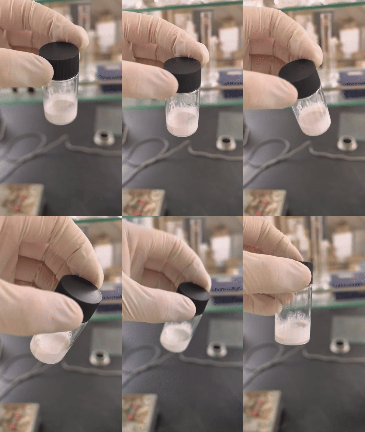
Figure 6: Suction filtration process of collecting FAS@BaTiO₃ powder (left); FAS@BaTiO₃ powder (middle); PC/FAS@BaTiO₃/PVDF-TrFE (right)
However, the testing results were still dissatisfying. Although FAS-17 surface modification improved the dispersion stability of BaTiO₃, the persistent dielectric loss indicated that suppressing aggregation alone was insufficient to achieve the electrical performance required for electrostatic actuation. After further research, I found that in addition to possible ionic conduction and interfacial polarization, the PVDF-TrFE/DMF solution introduced potential dielectric relaxation contributions associated with polymer segmental motion and dipolar reorientation of the polymer and solvent molecules. These processes dissipate energy when their polarization response lags behind the frequency of the applied field. Consequently, incorporating PVDF-TrFE could improve suspension rheology while introducing additional relaxation mechanisms, without necessarily suppressing charge transport or interfacial losses.
These considerations motivated my transition to fumed SiO₂ as a potentially more suitable stabilizer. A silica-based particulate network could inhibit sedimentation at rest while permitting flow under shear. This rheological behavior was expected to provide sufficient resistance to particle settling during storage, while allowing the network to rearrange under motion and thereby limit the viscous resistance imposed on the actuator. Moreover, this network can reduce reliance on dissolved polymer and eliminating the need for its DMF cosolvent. Replacing the PVDF-TrFE/DMF solution therefore offered a route to remove its associated relaxation contributions and reduce potential sources of ionic contamination while retaining mechanical stabilization. The expected advantage was taken as a more favorable balance between suspension stability, fluidity, and dielectric loss.

Figure 7: SiO2@BaTiO₃ (left two) and PDA@BaTiO₃ (powder)
However, subsequent dielectric measurements revealed an unexpected result: the loss tangent of the fumed-SiO₂/PEO formulation was higher than that of my earlier PVDF-TrFE-containing formulation. This finding challenged my initial expectation that replacing the fluoropolymer-based stabilization strategy with an inorganic particle network would reduce dielectric dissipation. The data showed that although the imaginary component of permittivity decreased, its relative reduction was smaller than that of the real component, resulting in a higher loss tangent. The decrease in imaginary permittivity was consistent with reduced overall dissipation, potentially from dielectric relaxation and interfacial polarization. However, the disproportionate decrease in real permittivity suggested that residual mechanisms, such as ionic conduction, may therefore have become relatively more significant, limiting the benefit of the revised formulation.

Figure 8: SiO2@BaTiO₃ (left two) and PDA@BaTiO₃ (powder)
03
Exploration on PC deionization
After further research, one possible causal is residual moisture. Although silica is electrically insulating in bulk, its large surface area introduces interfaces for water absorption. Moisture or soluble residues associated with these components might alter ionic dissociation and transport in PC, increasing the conductive contribution to the measured loss, highlighting the need to evaluate drying alongside coating procedure. The introduction of PEO also required closer examination. I had selected PEO to reinforce the silica network, yet its ether oxygen groups can coordinate existing cations and modify their local environment, which is revealed by the increase in dielectric loss compared to the group without PEO. Depending on the impurities present, these interactions could change the balance between ion association, immobilization, and transport. Consequently, a structure capable of resisting particle sedimentation might still permit appreciable ionic motion, confirmed by related PEO–silica research demonstrating that suspension stability and enhanced ionic conductivity can coexist in salt-containing electrolytes.
Taken together, these observations pointed to the availability of mobile ions as a potentially underlying limitation of the formulation. Moisture and PEO could influence ion dissociation, coordination, and transport, but these mechanisms depend on the presence of ionic species capable of carrying charge. This shifted my attention from modifying the pathways of ion transport to reducing the population of mobile charge carriers itself. Even a mechanically stable suspension could exhibit substantial conductive loss if sufficient ionic impurities remained in the liquid phase.
I therefore identified the deionization of PC, the continuous liquid medium, as a necessary next step to investigate. Reducing its ionic impurity content could limit the conductive loss associated with moisture-assisted dissociation and PEO-mediated changes in ion transport. This approach would complement drying and particle purification, since subsequent additions could reintroduce water or ionic residues. With this reasoning, I began exploring methods for removing ionic impurities from PC while preserving its suitability as the dielectric medium, aiming to determine whether improved electrical purity could resolve the loss that formulation changes alone had failed to suppress.
My first purification attempt combined drying with nanoparticle-assisted ion adsorption. I initially treated PC with molecular sieves to remove residual moisture, then added nanodiamonds, stirred the suspension, and removed the particles by centrifugation. The rationale was to address both the environment that facilitates ionic dissociation and the mobile impurities themselves. Molecular sieves were intended to reduce water content, while nanodiamond surfaces were expected to adsorb a fraction of the ionic contaminants, allowing their removal together with the particles. Reports of ion trapping by nanodiamonds in liquid crystals provided a basis for investigating this approach, although its effectiveness in PC required experimental evaluation. Singh et al., 2025

Figure 7: The nanodiamond with around 5nm diameter was dispersed into PC, stirred for 12h to fully absorb ion, and then removed from PC through centrifugation
I next explored capacitive deionization (CDI). I prepared a slurry containing activated carbon, carbon black, and PVDF binder and coated it onto titanium plates to fabricate opposing electrodes. Activated carbon provided a porous surface for ion adsorption, carbon black improved electrical connectivity within the coating, and PVDF bound the carbon particles together and to the current collector. I assembled the electrodes in a chamber made from acrylic plates and TPU gaskets and applied an electric potential across them. The intended mechanism was the migration of cations toward the negatively polarized electrode and anions toward the positively polarized electrode, followed by electrosorption within the electrical double layers of the porous carbon. This offered a way to retain contaminants on fixed electrodes while recovering the treated liquid. Hussain et al., 2022
In practice, however, the integrity of the electrode coating became the main limitation. During operation, substantial amounts of carbon detached from the titanium plates and dispersed into PC. This introduced an additional electrical concern: conductive particles suspended in the dielectric could contribute to interfacial polarization and, depending on their concentration and aggregation, facilitate leakage paths for electrons. Attempts to remove the detached carbon by centrifugation and vacuum filtration did not completely clear the liquid. The experiment therefore exposed a practical requirement beyond adsorption capacity: the purification medium also had to remain mechanically intact and be cleanly separable from the solvent. Because my CDI assembly did not meet that requirement, I moved to a third approach based on ion-exchange resins.


Figure 8: Deionizing active carbon, carbon black and PVDF were mixed in a scale of 2:1:1, and then painted on a titanium plate with a coating rod. The coated plate was then dried for 12 hours


Figure 9: The coated titanium plate was then assembled with laser cut acrylic plates to make a CDI. A 30V voltage is connected to the two electrodes of the plate as anode and cathode
For this approach, I selected Purolite A100Plus and C104Plus to provide complementary functionalities for capturing different ionic contaminants. A100Plus is a macroporous polystyrenic weak-base resin containing tertiary amine groups in the free-base form. Its amine sites can take up acids through protonation, retaining the associated anions. C104Plus is a porous polyacrylic weak-acid resin containing carboxylic acid groups in the hydrogen form, which can exchange hydrogen ions for suitable cations under favorable chemical conditions. Their complementary chemistry made them candidates for addressing both sides of the ionic impurity population. The manufacturer also identifies mechanical strength and resistance to organic fouling as advantages of A100Plus.
Their bead form offered a practical advantage over dispersed nanodiamonds and fragile carbon coatings: the treatment medium could be retained and separated more readily, and ion uptake did not require an externally applied voltage. Selecting the hydrogen and free-base forms also avoided deliberately introducing sodium or chloride counterions through the corresponding salt-form resins. Nevertheless, I could not assume that this weak-acid/weak-base combination would remove every dissolved salt. Its effectiveness in PC depended on impurity speciation, acid–base equilibria, resin wetting, and access to internal functional groups. Resin conditioning and moisture control therefore remained part of the purification problem.

Figure 10: PC with ion-exchanging resins submerged
After resin treatment, the measured loss tangent was approximately 0.5 at 1 kHz. Although this represented a marked improvement over the initial value near 6, the remaining loss was still substantial and fell short of the low-loss behavior I sought from solid ferroelectric polymers such as PVDF-TrFE or suitable PZT ceramics. This comparison served as a material-selection benchmark rather than a universal distinction between liquids and solids, since dielectric loss depends on composition, frequency, temperature, and field amplitude. The residual value also could not be assigned entirely to remaining ions; interfacial polarization and other contributions to the measured response could persist after purification.
I therefore investigated other high-permittivity liquid media, including formamide and mixtures of ethylene carbonate and PC, but obtained broadly similar outcomes under the conditions I explored. Changing the liquid medium therefore did not resolve the central difficulty of achieving sufficiently low loss while retaining the required dielectric response and practical processability. These experiments did not establish an intrinsic loss limit for polar liquids, but they showed that the liquid formulations and purification methods available to me were not delivering the combination of properties needed for the actuator.
This prompted a more fundamental reconsideration of the material architecture. I had originally relied on a liquid dielectric to provide both electrical polarization and lubrication between moving surfaces, so I need to reconsider whether the lubrication function actually required a liquid phase. A solid ferroelectric material with suitable surface properties might provide the required polarization while supporting low friction sliding, eliminating the need to maintain a stable suspension of dense ceramic particles leading to viscosity. I therefore shifted my research toward ferroelectric solids capable of providing a lubricating interface. The new objective was to combine dielectric performance with low friction and adequate wear resistance, treating the mechanical behavior of the contact surface as an essential part of the material design.


DOI: 10.1177/02783649211002545
Figure 10: The stator electrodes on ITO-PEI film was cut using laser ablation with a 50um width and 100um pitch (left two)

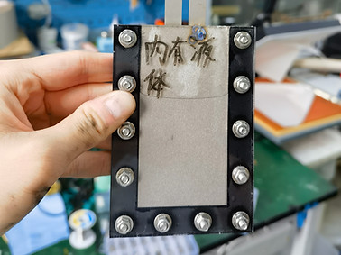
Figure 11: The electrodes are assembled with laser cut acrylic frame with PC/SiO2/SiO2@BaTiO3 dielectric liquid coated between the interface to build an electrostatic linear actuator. The slider between the two stators failed to move under the voltage calculated with the real part of the liquid, revealing the massive energy loss due to the imaginary part, according with the high dielectric loss tested. Moreover, the friction between the slider and stators was higher than expected due to the viscosity of liquid, which may be the secondary reason of moving restriction, making me consider the lubricating mechanism without liquid
04
Third trial with solid dielectric film

I first explored a sol–gel route followed by thermal treatment and sintering to produce a solid BaTiO₃ ceramic coating. This approach was intended to place the ferroelectric ceramic directly at the sliding interface. I prepared a BaTiO₃ precursor sol using barium acetate and titanium isopropoxide as barium and titanium source. Additionally, Ni–P–G composite coatings were prepared using an aqueous electroless plating bath containing nickel sulfate, sodium hypophosphite, and dispersed graphene at concentrations ranging from 30 to 300 mg/L, with the aim of balancing coating toughness and lubricating performance. The BaTiO₃ film served as the dielectric layer on the stator ITO electrodes, while the Ni–P–G coating was applied to the slider electrodes without an underlying BaTiO₃ layer. This configuration was intended to reduce friction and protect the BaTiO₃ film through graphene lubrication while retaining the mechanical integrity of the Ni–P matrix.


Figure 12: BaTiO₃ precursor gel prepared via the sol–gel method (left) and electroless Ni–P–G plating baths containing different concentrations of dispersed graphene (right)
However, a preliminary manual sliding test revealed substantial detachment of the Ni–P–G coatings within approximately 20 strokes over 10 s for all samples. Coating debris transferred onto the sintered BaTiO₃ surface, potentially forming conductive bridges between electrodes of different phases and causing interphase short circuits. A corresponding test against bare ITO produced noticeably greater sliding resistance and visible wear of the BaTiO₃ film, indicating inadequate sliding durability for both tested interfaces. This result made me returned to the PVDF family of polymers, seeking a matrix that could accommodate the ceramic filler while providing a more durable contact surface.


Figure 13: BaTiO₃ surfaces after sliding contact with Ni–P–G coatings prepared using graphene concentrations of 300 mg/L (left) and 30 mg/L (right) in the plating bath. The dark regions correspond to Ni–P–G coating material transferred onto the BaTiO₃ surfaces. Although reducing the graphene concentration decreased material transfer, visible residues persisted and sliding resistance increased noticeably, suggesting that the tested interfaces were unsuitable for prolonged actuator operation due to conductive debris accumulation and excessive friction.
Among the formulations I tested, the combination of PVDF-TrFE-CTFE and FAS-17-modified BaTiO₃ gave the most promising overall results. Following drying and annealing to promote crystallization, the composite formed a smooth, tough film. The slim, unsaturated hysteresis loop exhibits a predominantly reversible dielectric response with a possible contribution from ferroelectric polarization, leading to the expectation that further optimization of interfacial coupling between the BaTiO₃ particles and the continuous PVDF–TrFE–CTFE matrix may enhance the ferroelectric behavior, thus improving effective dielectric permittivity. The reported dielectric loss tangent below 0.1 from the graph below indicates a relatively small dissipative component of the dielectric response, which is favorable for limiting dielectric heating during alternating-field operation and supports the composite’s potential as a dielectric material for electrostatic actuators. The low loss was consistent with a sufficiently well-controlled interface to avoid excessive interfacial dissipation under the measurement conditions, although additional characterization would be needed to establish an improved filler dispersion and interfacial adhesion quality.

Figure 14: Polarization–electric field (P–E) response of the BaTiO₃/PVDF–TrFE–CTFE composite under a bipolar voltage amplitude of 1000 V at 1000 Hz.
This formulation offered a practical route toward combining the polarization response of a ceramic–polymer composite with the mechanical integrity required for a sliding dielectric film. It also allowed me to reconsider how lubrication should be incorporated. I used a coating bar to apply an approximately 2 μm layer of silicone oil to the film surface. In my tests, this lubricated surface performed more satisfactorily than either of the two liquid formulations I had previously prepared. No observable swelling of the film occurred during the test period, encouraging further evaluation of its compatibility with the lubricant and its potential for sustained operation.
The resulting approach assigned complementary functions to the two layers: the solid composite provided the principal dielectric medium and mechanical support, while the thin silicone-oil layer reduced friction at the moving interface. Its eventual electrical performance would nevertheless need to be evaluated as a complete layered structure, since the lubricant also occupies part of the electrode gap and influences the electric-field distribution.
Time constraints prevented me from integrating this film into the actuator, for I got only one summer to conduct this research. Its observed mechanical integrity, polarization response, low dielectric loss, and compatibility with the lubricating layer, providing a basis for pursuing that next step. I am particularly interested in determining whether these material-level advantages translate into useful actuation force, low energy dissipation, and durability under repeated sliding. Incorporating the lubricated composite film into a working actuator remains the next stage I hope to pursue.


Figure 15: PVDF–TrFE–CTFE/FAS-17@BaTiO₃ composite film obtained by drying the self-leveled casting solution on a glass substrate, then carefully peeled from the glass substrate using tweezers before annealing


Figure 16: The PVDF–TrFE–CTFE/FAS-17@BaTiO₃ film was secured under tension on a steel frame before annealing. Thermal treatment was performed with the film constrained to maintain its geometry and promote the relaxation of residual stresses introduced during casting and drying.

Figure 17: Following annealing, a gold coating was deposited on the composite film by chemical vapor deposition (CVD) to form a conductive electrode for subsequent dielectric tests.